Some handy tips to study civil engineering drawings and details
In this construction video tutorial, the eminent engineer Sami Ullah, teaches you how to inspect civil engineering drawings and details.
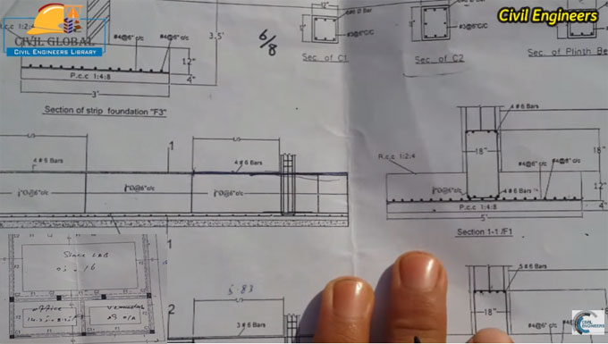
The video starts with ground floor foundation plan and then proceed to section of strip foundation.
The purpose of these drawings is to provide detail information on all things in a construction site to a civil engineer. Besides, one can get superior conception on the building plans.
Most engineering drawings are formed in "scale" versions of 1/4-1/8 inches (.55-.275 centimeters) per foot, other scales may also be applied for very large foundations. The scale of the drawing should be defined prior to examine it thoroughly. If the scale is not clearly visible on the drawing, talk with the concerned engineer for amendment.
Lots of symbols are also utilized in the engineering drawing which range from rectangles, circles, and triangles. These drawings provide huge benefits to read engineering drawings.
The engineering drawings are usually created on a scale tool small that producing detail becomes very difficult.
Owing to this, engineers frequently include circled numbers to specific parts of the drawings. These circled numbers specify that the area recognized is exposed in superior detail on another page.
Abbreviations are also very helpful for engineers as these can specify shapes, processes, and even dimensions via a few letters. Some of the most common abbreviations applied in engineering drawings are DP, that denotes depth, and DIA, that stands for diameter.
To learn the detail process to study drawing, watch the following video tutorial.
Video Source: Sami Ullah


