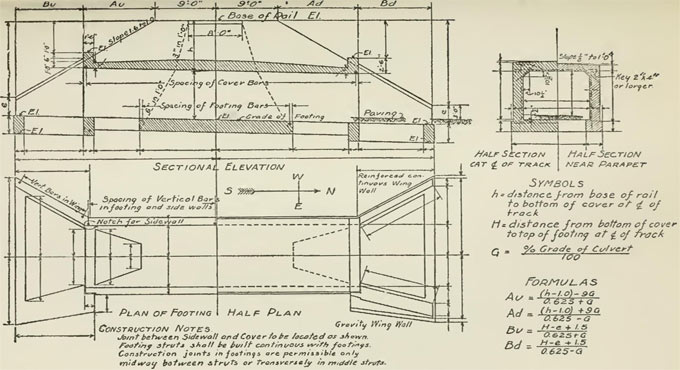
Details of standard drawings in Concrete Culvert Design
Given below, a recommended method for accomplishing the drawing toward standard rigid frame open footing culverts, SS114-1, without any skewed end, retaining walls or other special features:
- Acquire culvert size, length, and height of fill from ?Design Data Form for Concrete Culverts?.
- Choose proper standard drawing for rigid frame open footing culvert.
- Find out from ?Design Data Form for Concrete Culverts? to verify that culvert is an extension or not:
If culvert is an extension, modify vertical centreline on left side of section detail 1 to a solid line and mark as - "END OF EXISTING CULVERT".
Include length of culvert extension on the horizontal dimension line:
Namely, 16 m EXTN RT
17 m EXTN LT
If culvert is not an extension, mark center line as "Centre-Line Highway" and add culvert length each side of Centre-Line Highway.
Namely, 16 m RT
17 m LT
- Choose from Division 5 correct detailing table for necessary size of culvert.
- Include span and height of culvert and dimensions of top slab, haunch and wall on "Typical Culvert Section" detail.
- Find out maximum soil bearing pressure with adherence to Section 5.2.
- Find out necessary footing width and include footing dimensions on "Typical Culvert Section" detail. The dimension that illustrates the footing projection may be originated from the following expression:
Include bar size and/or spacing for H, J, K and P bars where necessary on all details. Keep in mind that P bar spacing is at mid-span.
Include spacing for V bars as well as Y bar size on Detail B.
- Include bar size and spacing for T bars.
- Include dimensions on Detail 2 for layout of P bars, remember in mind that smaller dimension is half of the wall thickness and larger dimension is P bar length.
- Include supplementary P bar at each end of culvert where no header wall is necessary.
- Include header walls where necessary as mentioned in Sections 4.2.6. Accomplish steel bar table for culvert and for header wall.
- Multiply unit quantities with culvert length.
- Estimate modifications to steel and concrete quantities required if actual footing size surpasses minimum footing size and adjust unit quantities provided.
- Add adjustment to steel quantity for R and W bar laps. Add adjustment to footing concrete quantity for 100 mm lip at each end of footings.
- Add header wall quantities where appropriate.
- Include total quantities in ?Culvert Quantities? table on standard drawings.
- The Standard Drawing should have been sealed, dated and signed with adherence to 4.3.1.


