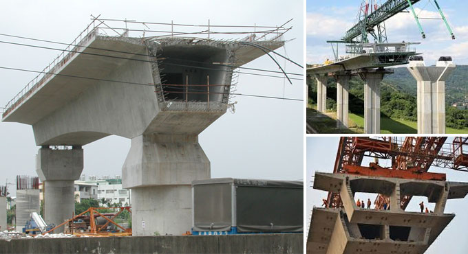
Analysis of Prestressed Concrete Box Girder Bridge
A box girder bridge is a special type of bridge in that beams have to compromise girders in the shape of empty box. Bridge construction has got a paramount importance worldwide. Box girder is achieving popularity in bridge engineering because of its stability, economy, structural efficiency.
Calculation of Ultimate Strength
(a) Failure by yield of steel (under-reinforced section)
Mult = 0.9dbAsFp
Here,
As = the area of high tensile steel
Fp = the ultimate tensile strength for steel without definite yield point or yield stress or stress at 4 per cent elongation whichever is higher for steel with a definite yield point.
db = the depth of the beam from the maximum compression edge to the centre of gravity of the steel tendons.
(b) Failure by crushing concrete
Mult = 0.176 bdb2fck
Where,
1. b = the width of rectangular section or web of beam
2. fck= characteristics strength of concrete
3. G = Calculation of Section un- cracked in flexure
4. b = width in the case of rectangular member and width of the rib in the case of T, I and L beams
5. d = overall depth of the member
6. fcp = compressive stress at centroidal axis due to prestress taken as positive.
(c) Analysis and Design of Post-Tensioned Deck type Box-Girder Bridge
A post- tensioned deck type Box ? Girder
Bridges of clear span 30m and width of roadway is 7.5m. Assume Live Load as per IRC: 6-2000 vehicle is passing over deck given in the chapter 4. The Bridge analysis for different L/d ratio starting from 15 to 20 and different L/d ratio considered are as follows:
Case 1 L/d= 19, d = 1.6
Case 2 L/d =18, d = 1.7
Case3 L/d = 17, d = 1.8
Case4 L/d= 16, d= 1.9
Case5 L/d= 15, d=2.0
Preliminary Data
1. Clear span = 30m
2. Width of roadway = 7.5 m
3. Overhang from face of girder = 1.2m
4. Deck thickness = 0.2 m
5. Bottom slab thickness = 0.2 m
6. Girder thickness = 0.3 m
7. The tendon profile is considered as parabolic in nature.
As per IRC:18-2000
fck= 50 Mpa,
fci = 0.8
fck = 40 Mpa,
fct = 0.5
fci = 20 Mpa,
fcw = 0.33
fck = 16.5 Mpa
ft = 1/10
fct = 2.0 Mpa
ftw = 0
As per IS:1343-1980
Ec = 5700
fck1/2 = 40.30 kN/m2
fp = 1862 Mpa,
n = 0.85,
E = 2?105 Mpa
Validation of Results
Table of Calculation of Prestress Losses - (As per IS:1343-1980)
| Span (m) | ^S | ^C | ^E | ^A | ^F | ^R | Total | n |
| 0.0L | 8E-05 | 0.0 | 0.0 | 0.0 | 0.0 | 90 | 90 | 0.95 |
| 0.0L | 2.6 | 2.3 | 78 | 9.7 | 90 | 182.6 | 0.9 | |
| 0.0L | 2.6 | 2.4 | 39 | 22 | 90 | 155.8 | 0.91 | |
| 0.3L | 2.6 | 2.4 | 26 | 36.7 | 90 | 157.7 | 0.91 | |
| 0.4L | 2.7 | 2.5 | 20 | 54.3 | 90 | 169.0 | 0.9 | |
| 0.5L | 9.1 | 8.3 | 16 | 171 | 90 | 294.0 | 0.85 |
Where,
^S = Shrinkage
^C= Creep
^E = Shortening of concrete
^A = Slip in anchorage
^F = Friction
^R = Relaxation
n= Efficiency
After Losses, effective Prestressing Force
1. (P) = P (1-Losses) = 14011.51 kN
2. Table.7 Calculation of Stresses at top and bottom fiber
Compressive Stress at
1. Transfer = 6.66 < 0.5 fcj = 20 mpa
2. Service = 8.367 < 0.33 fck = 16.5 mpa
Tensile stress at
1. Initial Stage = 2.979 < 3mpa (As per IS:1343 ? 1980)
2. Working Stage = No tensile stress
Design of Reinforcement in Box Girder Bridge
P =14011.51 kN, d = 1350 mm, bw = 200 mm
Assume 150 mm wide and 150 mm deep distribution plate, located concentrically at centre.
ypo /y0 = 75/150 = 0.5,
As per IRC:18-2000, From table value of Fbst/ Pk = 0.17 and Fbst = 452.753 kN
Using 12 mm diameter links, area of steel links is,
Ast = 1254 mm/2
Providing 24 bars of 12 mm dia, 750mm also bar of 12 mm dia @ 110 mm c/c horizontally to form
mesh.
Side Face Reinforcement
As per clause 18.6.3.3 of IS:1343-1980
Ast = 0.05 x 1350 x 300/100 = 202.5 mm/2
Provide 6 ? 12 mm dia on each face of web
Design of Deck Slab
Using M30 grade concrete and Fe415
Total moment due to DL+SIDL+LL = 1427.0 kN.m
Depth required = 150.4 < 250 mm
Main Reinforcement
Ast = 3192.6824 mm/2
Providing 16mm? bars dia 100 mm c/c
Design of Transverse Reinforcement
M = 0.3ML + 0.2(MDL + MSIDL)
M = 324 kN.m
Ast = 724.74 mm/2
Providing 12 mm dia bars @ 160 mm c/c
(d) Comparsion of Result for Various Span/Depth Ratio
The comparison of prestress force, deflection and stresses values are obtained for various span/depth ratio (table no. 10 & 11) for box girder bridge. The values are calculated as per IS:1343-1980.
Permissible (DL-Prestress Force) = 12 mm
Permissible (DL-LL-Prestress Force) = 85.7 mm


