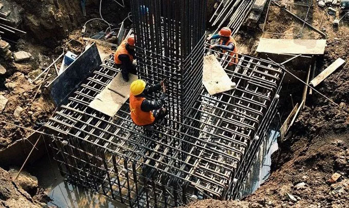
How to design footing following specifications as per IS 456 : 2000 Specifications
The design of isolated footings is based on the following IS 456 : 2000 standard
1. General: Footings are designed to retain the employed loads, moments and forces and stimulate reactions and to make sure that any probable settlement should be as almost consistent as possible, and the safe bearing strength of the soil is not surpassed (as per IS 1904).
1.1 In sloped or stepped footings the operative cross-section in compression shall be restricted by the area located over the neutral plane, and the angle of slope or depth and location of steps should be arranged in such a manner so that the design requirements are met at each section. Sloped and stepped footings are designed as a unit and shall be built up to ensure action as a unit.
1.2 Thickness at the Edge of Footing
In reinforced and plain concrete footings, the density at the edge should not be under 150 mm for footings on soils, nor below 300 mm over the tops of piles for footings on piles.
1.3 For plain concrete pedestals, the angle among the plane penetrating the bottom edge of the pedestal and the related junction edge of the column with pedestal and the horizontal plane (as per Fig. 20) should be directed by the expression:
2. Moments and Forces
2.1 For footings on piles, calculation for moments and shears are dependent on the presumption that the reaction from any pile is centralized at the centre of the pile.
2.2 To calculate stresses in footings that support a round or octagonal concrete column or pedestal, the face of the column or pedestal should be considered as the side of a square transcribed inside the boundary of the round or octagonal column or pedestal.
2.3 Bending Moment
2.4 The bending moment at any section should be defined by penetrating the section a vertical plane that expands entirely over the footing, and calculating the moment of the forces functioning over the whole area of the footing on one side of the stated plane.
2.5 The maximum bending moment being applied in creating the design of an isolated concrete footing that supports a column, pedestal or wall, should be the moment calculated in the manner set in 34.2.3.1 at sections situated as follows:
a) At the face of the column, pedestal or wall, for footings which support a concrete column, pedestal or wall;
b) Midway among the centre-line and the edge of the wall, for footings below the masonry walls
c) Midway among the face of the column or pedestal and the edge of the gusseted base, for footings below gusseted bases.
For more information, go through the following article brainkart.com


