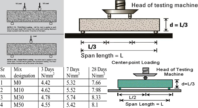
Flexural Strength Test of Concrete as per Code (IS:516-1959)
The Flexural Strength of Concrete starts to happen when a road slab with insufficient sub-grade support is exposed to wheel loads and / or there are volume changes because of temperature / shrinking.
REFERENCE STANDARDS: IS: 516-1959 ? Methods of tests for strength of concrete.
TOOLS & APPARATUS:
1. Beam mould with size 15 x 15x 70 cm (when size of aggregate is under 38 mm) or with size 10 x 10 x 50 cm (when size of aggregate is under 19 mm).
2. Tamping bar (40 cm long, weighing 2 kg and tamping section with size of 25 mm x 25 mm).
3. Flexural test machine? The bed of the testing machine should contain two steel rollers, 38 mm in diameter, on which the specimen should be supported, and these rollers should be mounted in such a manner that the distance from centre to centre remains 60 cm for 15.0 cm specimens or 40 cm for 10.0 cm specimens.
The load should be employed through two similar rollers mounted at the third points of the supporting span that is placed at 20 or 13.3 cm centre to centre. The load should be dispersed evenly among the two loading rollers, and all rollers should be mounted in an efficient manner to use the load axially and without exposing the specimen to any torsional stresses or restraints.
Laying bricks and blocks:
METHOD:
1. Arrange the test specimen by filling the concrete into the mould in 3 layers maintaining similar thickness roughly. Apply tamping bar to tamp each layer 35 times. Tamping should be divided consistently over the whole crossection of the beam mould and all through the depth of each layer.
2. Cleanse the bearing surfaces of the supporting and loading rollers , and eliminate any loose sand or other material from the surfaces of the specimen where they are in touch with the rollers.
3. Circular rollers formed with steel contain cross section with diameter 38 mm. It should be applied for giving support and loading points to the specimens. The length of the rollers should be minimum 10 mm surpassing the width of the test specimen. A total of four rollers should be utilized, three out of which should have the capacity for being rotated along their own axes. The distance among the exterior rollers (i.e. span) shoud be 3d and the distance among the inner rollers shall be d. The inner rollers should be evenly placed among the exterior rollers in order that the whole system remains systematic.
4. The specimen preserved in water should be examined instantly while removing from water; when they are still wet. The test specimen should be arranged in the machine properly centered with the longitudinal axis of the specimen at correct angles to the rollers. In case of moulded specimens, the mould filling direction should be normal to the direction of loading.
5. The load should be employed at a rate of loading of 400 kg/min for the 15.0 cm specimens and at a rate of 180 kg/min for the 10.0 cm specimens.
CALCULATION:
The Flexural Strength or modulus of rupture (fb) is provided as
fb = pl/bd2 (when a > 20.0cm for 15.0cm specimen or > 13.0cm for 10cm specimen)
or
fb = 3pa/bd2 (when a < 20.0cm but > 17.0 for 15.0cm specimen or < 13.3 cm but > 11.0cm for 10.0cm specimen.)
Where,
a = the span among the line of fracture and the nearer support, calculated on the center line of the tensile side of the specimen
b = width of specimen (cm)
d = failure point depth (cm)
l = supported length (cm)
p = max. Load (kg)


