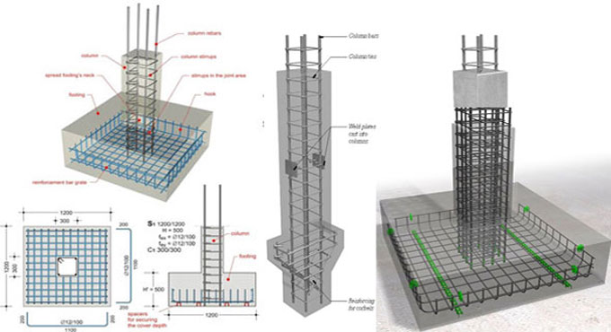
Guidelines for rebar detailing of RCC structures
Reinforcement Detailing or Rebar detailing is a detailed construction engineering process normally accomplished by the Rebar fabricators, structural engineering consultants or the contractors for generating ?shop/placing? drawings or shop drawings and bar bending schedule of steel reinforcement for construction. Architect/Engineers(A/E) produce ?Design Drawings? with the purpose of adding strengths with rebar size, spacing, location, and lap of steel.
Rebar Detailing is also known as Rebar scheduling, RC Detailing and Bar Bending schedule predation, RC Drafting, etc in different countries.
Objective of Rebar Detailing - The rebar detailing is done for the following purposes :
a) To produce an error-free Bar bending schedule, when fabricated should be accommodated in the concrete formwork devoid of any issue. The similar Bar Bending Schedule should be utilized for accounting and invoicing.
b) To develop a detailed Rebar placing drawing (known as Rebar Shop drawings). This Rebar placing drawing assists an Ironworker to place rebar perfectly in the site efficiently.
c) To allow the structural engineer to verify and approve when the structural design intent is precisely transformed into the Rebar Placing drawings and Bar bending schedules.
d) To perform a Rebar wastage analytics and minimize probable scrap existing in the Drawing level.
Standard Hooks: The term ?standard hook? is defined as follow -
1. 180o bend together with an extension of minimum 4 bar diameters, but not below 65 mm at the free end of the bar.
2. 90o bend together with an extension of minimum 12 bar diameters at the free end of the bar.
3. For stirrup and tie anchorage.
For 16 mm f bar and smaller, a 90o bend along with an extension of minimum 6 bar diameters at the free end of the bar,
a. For 19 mm to 25 mm f bars, a 90o bend together with an extension of minimum 12 bar diameters at the free end of the bar,
b. For 25 mm f bar and smaller, a 135o bend along with an extension of minimum 6 bar diameters at the free end of the bar,
c. For closed ties and constantly wound ties, a 135o bend along with an extension of minimum 6 bar diameters, but not below 75 mm.
Minimum Bend Diameters: The minimum diameter of bend is calculated on the inside of the bar, for standard hooks except for stirrups and ties in sizes 10 mm f through 16 mm f, should not remain under the values provided in Table below.
For stirrups and tie hooks, inside diameter of bend should not be lower than 4 bar diameters for 16 mm f bar and smaller. For bars greater than 16 mm f, diameter of bend should be as per the table given above.
Inside diameter of bend in welded wire reinforcement for stirrups and ties should not be lower than 4 bar diameters for deformed wire greater than MD40 and 2 bar diameters for all other wires. Bends with inside diameter of lower than 8 bar diameters shall not remain under 4 bar diameters from adjacent welded intersection.
Bending: Normally, all reinforcement should be bent cold. Reinforcement partly implanted in concrete should not be bent in place, apart from approved by the engineer or as demonstrated in the design drawings.
Surface Conditions of Reinforcement: After arranging the concrete, metal reinforcement does not contain any mud, oil, or other nonmetallic coatings which make the bond weak. Epoxy-coating of steel reinforcement compliant with standards referenced in this code should be employed.
Metal reinforcement with rust, mill scale, or a mixture of both, should be recommended, on the condition that the minimum dimensions (along with height of deformations) and weight of a hand-wirebrushed test specimen are not lower than standard ASTM specification requirements.
To get more details on placing and spacing of reinforcement, go through the following article. thecivilengineering.com


