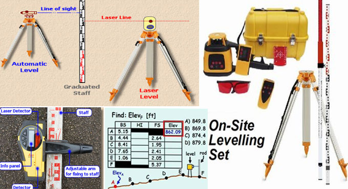
The process to make calculation with a Surveying Laser Level
The purpose of leveling is to determine the variations in height among two points ? as for instance, the surface of a river and the top of a levee, or ground level and a hilltop. To avoid systematic errors pertaining to climatic conditions or to residual line-of-sight error, the instrument should be arranged with equal distance from the two points. To make exact horizontal and vertical calculations, a basic reference point should be created by altering the level to maintain the accuracy to the actual horizontal and vertical planes.
Height Difference Among 2 Points:
To work out the variation in height, get the difference among staff readings for the backsight (A) minus the foresight (B).
Calculate The Distances Optically with the Level:
The vertical cross-hair of the reticle (the viewfinder's internal target) is passed by two short stadia lines parallel to the horizontal cross-hair. Go through the eyepiece and record the distance among the upper stadia line and the horizontal cross-hair. Now, read the distance among the horizontal cross-hair and the lower stadia line. Deduct the lower distance from the upper and multiply with 100 to get the distance reading.
Line Leveling:
If points A and B situate far away, the height difference among the two points will be obtained by line leveling. Apply target distances normally among 30-50 meters. Measure the distances among the instrument and the two staffs; they should be equivalent.
Determine the Height Difference:
1. Install the instrument at S1.
2. Settle the staff in proper manner vertically at point B; read off and note down the height (backsight R).
3. Settle the staff at the turning point 1 (ground plate or prominent ground point); read off and note down the height (foresight V).
4. Install the instrument at S2 (the staff persists at the turning point 1).
5. Rotate the staff at the turning point 1 with caution in order that it faces the instrument.
6. Read off the backsight and do the process again (S3, S4, etc.) as necessary unless you get to the end.
7. The variation in height among A and B is equivalent to the sum of the backsight and the foresight.
Staking Out Point Heights:
Suppose, there is an excavation, where point B should be set out one meter under street level. Calculate it in the following manner:
1. Prepare the level in order that the sighting distances to points A and B remain the same.
2. Settle the staff at point A and read off the backsight R.
3. Now settle the staff at B and read off the foresight V. To determine the variation h from the required height at B, apply the formula h = V - R - ?H.
4. Set in a post at point B and demarcate the necessary height.
5. The task can also be performed by working out the necessary staff reading in advance. Apply the formula V = R - ?H. Then, shift the leveling staff up or down unless you can read off that necessary value in the level.
Longitudinal and Transverse Profiles:
If it is required to plan and track a communications route (e.g., a road), measure fill, and/or adjust the route to the topography so far as possible, apply longitudinal and transverse profiles.
Longitudinal Profiling:
Track and station the longitudinal axis by setting up and demarcating points at equal spaces. Apply the line level to find out the heights of the station points. It belongs to the longitudinal profile.
Transverse Profiling:
At right angles to the roadline, record each of the station points and apparent topographic features.
Determine the ground heights for each of the points in the transverse profile, with the recognized instrument height:
1. Location of the staff at a specified station point. The instrument height is equivalent to the sum of the staff reading and the station point height.
2. At each point on the transverse profile, deduct the staff reading from the instrument height. It provides you the height of each point.
3. The distances can be calculated from the station point to each point in the transverse profile, either with surveyor's tape or optically with the level.
A longitudinal profile drawing will demonstrate the heights of the station points at a bigger scale (e.g., 10x) as compared to those in the longitudinal direction, that is associated with a round reference height.


